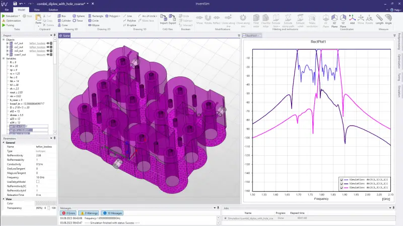
The modeling framework is based on a Constructive Solid Geometry (CSG) approach, in which structures are constructed starting with primitive shapes such as boxes, cylinders, and rectangles. Each primitive has a set of parameters that define its dimensions, allowing for easy parameterization. Additionally, Boolean operations (union or subtraction) can be applied to these primitives, enabling the rapid creation of moderately complex, parameterized structures. However, the CSG approach becomes overly restrictive when dealing with more intricate shapes. To address this limitation, sophisticated structures can be achieved by incorporating concepts from the Boundary Representation (BREP) approach. These concepts include rotations, mirroring, extrusions, cloning, and edge fileting. To overcome this constraint, the CSG capabilities in the geometry kernel have been expanded with BREP operations. Furthermore, users have the option to introduce multilevel relative coordinate systems, significantly enhancing the modeling capabilities.
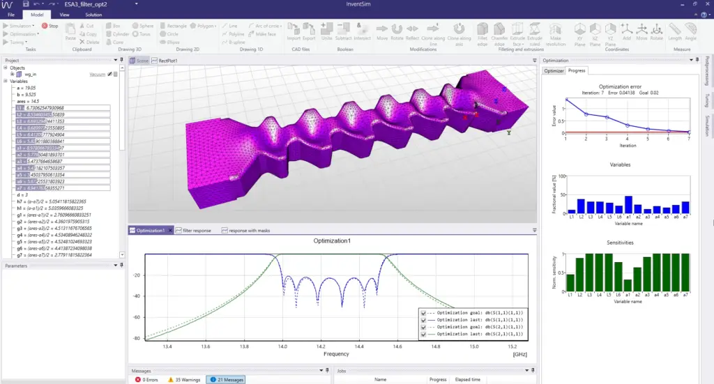
A crucial advanced capability of the geometry kernel within the framework is the ability to track deformations of geometries while maintaining their topological properties. This feature is paramount for efficient shape optimization. During optimization, the design variables – specifically, the parameters defining the structure – undergo alterations, necessitating the reconstruction of the geometry after each modification. Furthermore, in cases where gradient optimization methods are employed, the sensitivities of the objective function must be computed in every iteration. This process involves conducting multiple simulations of the structure with slight perturbations in the parameters. The deformations are monitored each time the geometry is perturbed, and this procedure is executed concurrently for the entire set of optimization parameters. The alterations in geometry are closely linked to mesh adjustments. Consequently, the need for numerous mesh regenerations is obviated. Instead, mesh generation occurs only once per iteration and is subsequently adjusted based on deformation data. Typically, only a small portion of the mesh requires modification; for example, certain vertices may be repositioned. This not only expedites computation but also enhances the accuracy of calculated design sensitivities, thereby effectively improving gradient optimization efficiency.
Selected features of geometry modeler:
- Basic 3D solids: box, cylinder, cone, sphere, torus
- Boolean operations: union, subtraction, intersection
- Basic 1D and 2D shapes: line, arc, polyline, B-spline, rectangle, circle, ellipse, polygon
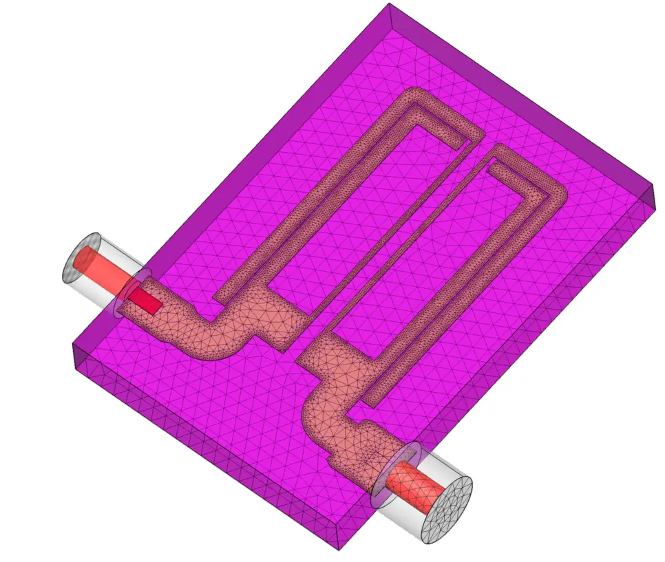
- Extrusion of 2D shapes
- Edge filleting and chamfering
- Nested, dependent and parameterizable coordinate systems
- Shape parametrization with variables
- Expressions including mathematical operators and functions
- Import/Export of 3D objects in STEP file format
- Unique shape deformation module for design of smooth-profile solids